
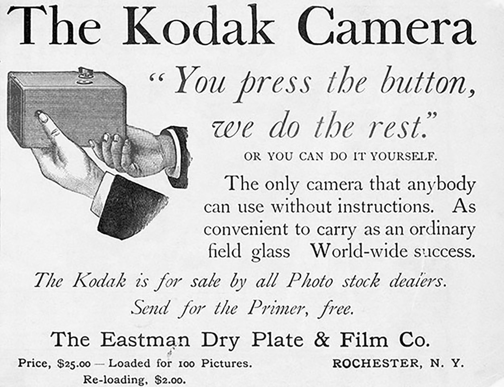
 Early Kodak add - You press the button, we do the rest.
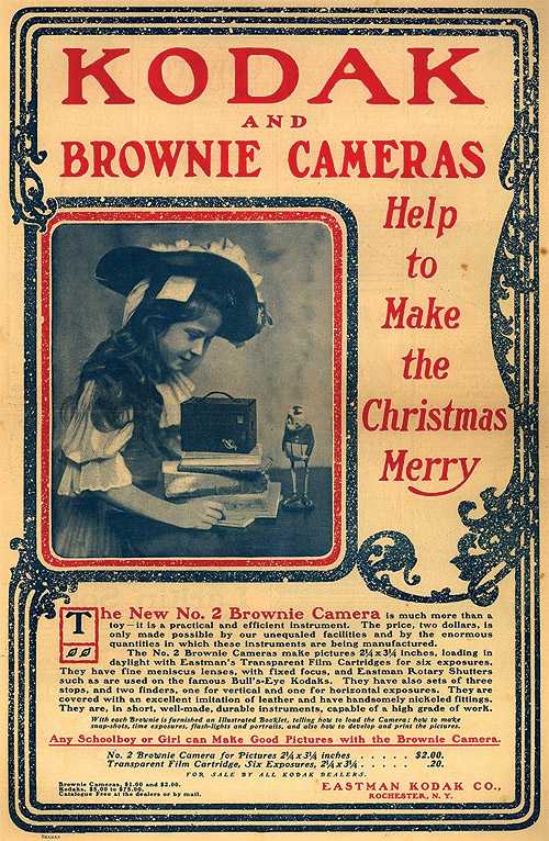
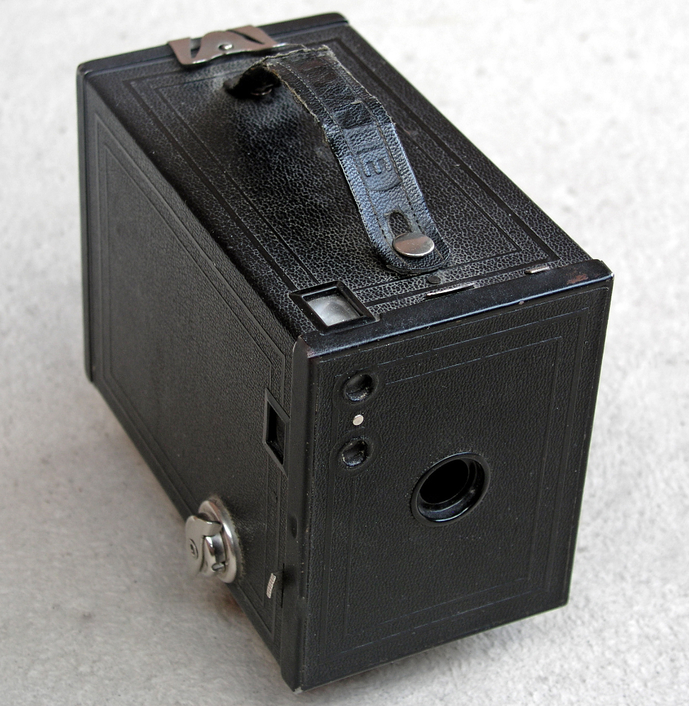
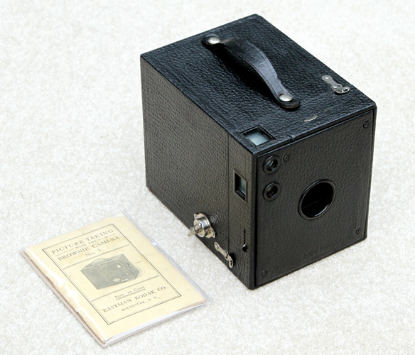
KODAK
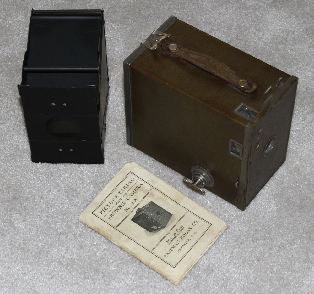
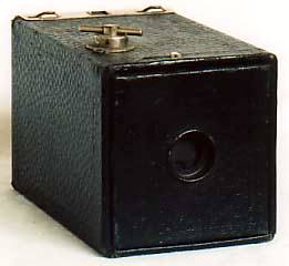
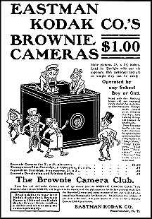
BROWNIE - 1900. The
Brownie is given credit for creating the hobby of photography as an
American national pastime early in the 20th Century. The film was
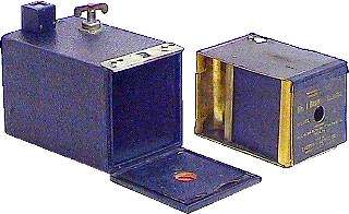
loaded into a removable film carrier/exposure chamber that slid into
the back of the camera. The third photo shows the film carrier
and the optional accessory viewfinder for the original and several
other Brownie models that clipped onto the box (25 cents
extra!). There are so many different Browie models and variations
of each model that a very extensive collection could be established
consisting of Brownie cameras only, and even more so if you would
include modern versions. The original Brownie Camera was only in
production for about four months and is quite rare today. Price
then, $1.00. Price now in excess of $1,000.
https://www.brownie-camera.com/5.shtml
http://www.nwmangum.com/Kodak/
https://www.brownie-camera.com/51.shtml
A.
A. CAMPBELL SWINTON AND ELECTRONIC PHOTOGRAPHY - 1908.
The first proposal for a workable system of electronic photography was
put forward in 1908 by a Scotsman, Alan Archibald Campbell Swinton, and
published in a journal called Nature - an idea for a device using an
electric
pickup tube for recording images. The camera was completely electronic,
producing images without any mechanical assistance apart from
focusing.
The system enabled images to be sent from point-to-point by cable, or
through
the ether using invisible waves. The process produced twenty-five
electronic images every second and was true multi-media, being
accompanied
by synchronized sound. Swinton's idea took twenty-four years to
become
a reality as the world's first system of electronic photography.
The system is still in use today - it's called television. Additional
information concerning Alan Archibald Campbell Swinton can be found at:
![]()
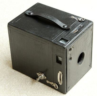
KODAK BROWNIE No. 3 - 1908-1934. The above model of No. 3 Brownie would date between 1908 and 1917 as the film tension spring is in the center rather than at the ends of the film spool. Those who collect old Brownies will recognize that the above sample is in rather excellent condition as the latches do not have even a trace of corrosion. Original price was $4, which would be about $88 in 2010 dollars. It was purchased on eBay with manual for $20.
http://www.brownie-camera.com/58.shtml
![]()
KODAK BROWNIE No. 3, Model B - 1911-1926. The Model B came out in 1911, but the one shown above is of 1920 or later since 1920 was the year when the trigger guard was added around the shutter lever.
http://www.brownie-camera.com/58.shtml
![]()
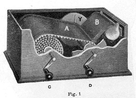
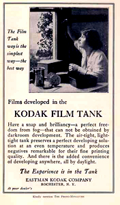
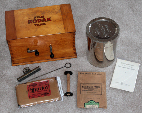
KODAK FILM TANK - 1918. The film tank is actually the round tank on the right. The box was used for winding film from the original roll onto a reel for developing as shown on the far right. The sawteeth on the underside of the roll permitted the developing fluids to reach the film once the reel was put into the developing tank. The entire process could be completed by the amateur in daylight.
http://www.lungov.com/wagner/c/072c.html
http://www.libraryweb.org/~digitized/tradecats/kodak/Kodak_picture_making_aids_1940.pdf
![]()
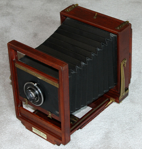
SENECA COMPETITOR - 1907-1925. The
Seneca Camera Manufacturing Company was located in Rochester, New York.
The Competitor was a 5 x 7 or 8 x 10 view camera used by professional
photographers. It came in two variatons: the cherry and brass model
shown above, and a less expensive model of light mahogany color with
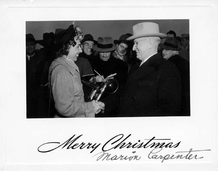
nickel plated steel parts. The personal photographer of President
Truman, Marion Carpenter (the first female White House photographer)
used a Seneca Competitor for her official White House Photographs.
http://camerapedia.wikia.com/wiki/Seneca
https://etchedinstone.org/31374/uncategorized/marion-carpenter/
![]()
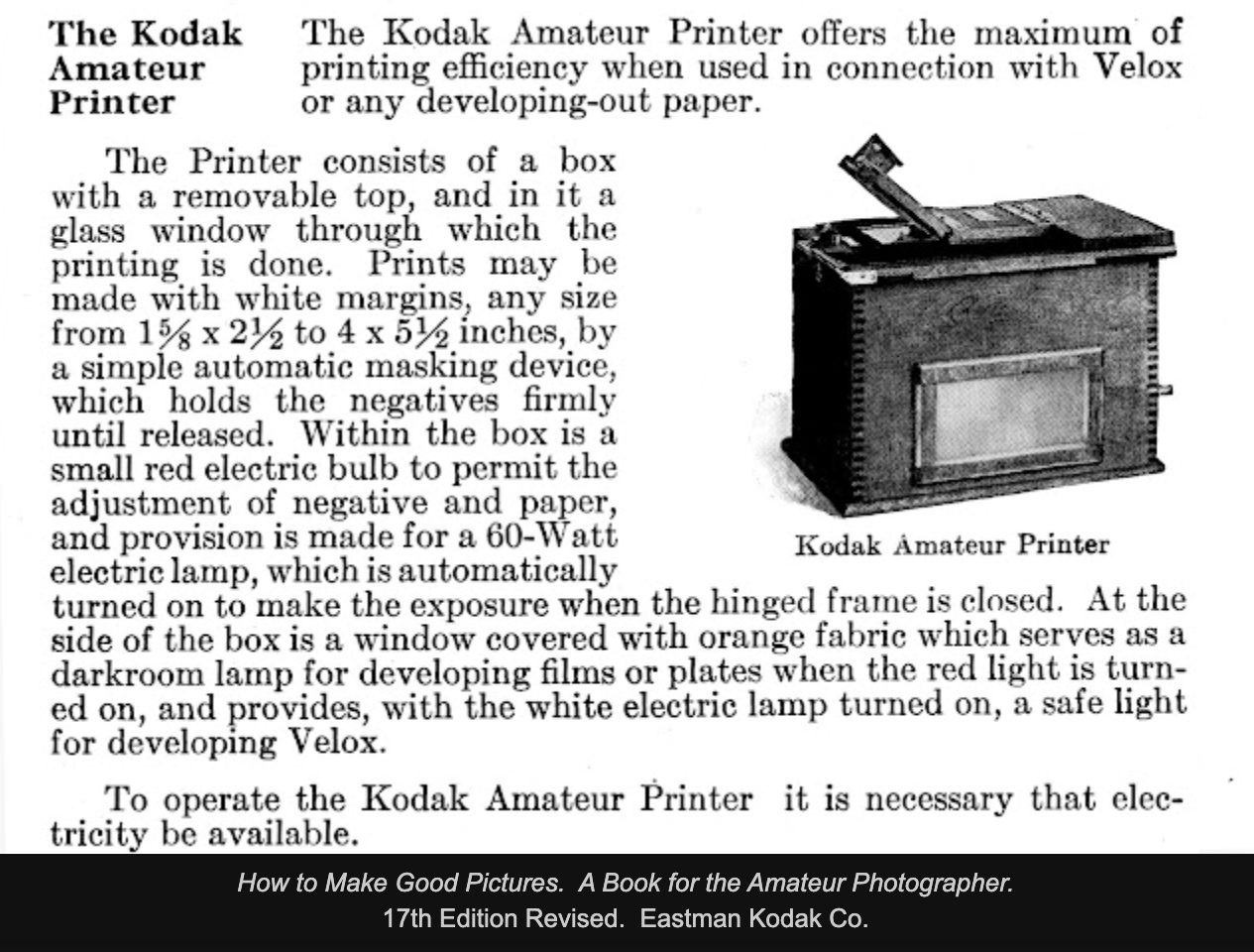
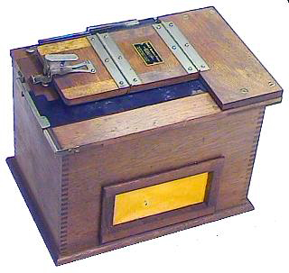
Be sure electricity is available!
KODAK AMATEUR PRINTER- 1914. A contact
printer for negatives up to 3 3/4 x 5 1/2 inches in size . It had an internal
safelight and built-in printing frame with adjustable masks. These
contact printers were frequently used to mass produce post cards in the
3 1/4-inch by 5-inch size at up to 300 cards per hour. Using a contact
printer in this way could provide an extra source of income for an
industrious photographer. Information kindly provided by Doug Mills
from the book "Fifty Dollars a Week with Car and Camera" by Paul Glenn
Holt.
http://progress-is-fine.blogspot.com/2017/12/kodak-amateur-printer.html
http://www.libraryweb.org/~digitized/tradecats/kodak/Kodak_picture_making_aids_1940.pdfA TRIO OF AMATEUR PRINTERS: The Kodak Amateur Printer is seen on eBay from time-to-time and can usually be purchased for $10-40 or so depending on condition. I purchased four amateur printers and used one for parts as I restored the others. Very little information is available concerning the Kodak Amateur Printers, but I believe the one below is an early model because it is more complex (more expensive to build) and the switching mechanism seems to be more finicky as to adjustment than other models.
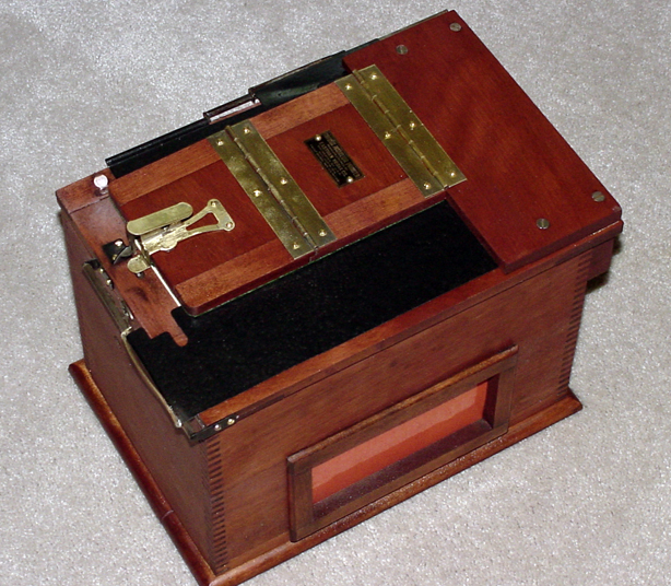
![]()
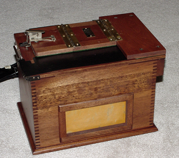
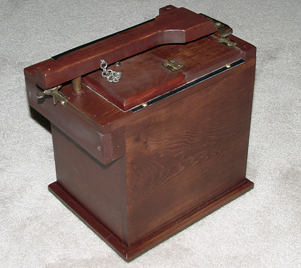
The above photo shows the exterior of the printer and the folding platen on top that holds the film and paper in place by way of the locking switch on the left. A small shaft protruding through the upper left is depressed to switch the safelight off and the white light on. The orange window on the side is removable and originally had a yellow cloth as a safelight media. In most of the Kodak Amateur Printers now available the cloth is severly damaged or missing. I replaced the cloth in this printer with a piece of laminated orange paper.
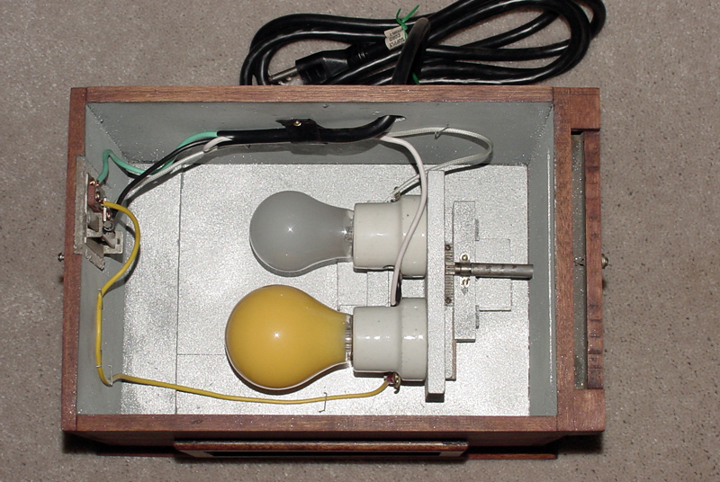
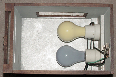
The second photo shows the interior and the mechanism for adjusting position of the lights. A shaft protrudes through the right and is turned to move the lights left and right (up and down in the photo). The shaft can also be moved in and out moving the bulbs toward or away from the switching mechanism on the left (left and right in the photo). The purpose was apparently to adjust for the various sizes of prints.
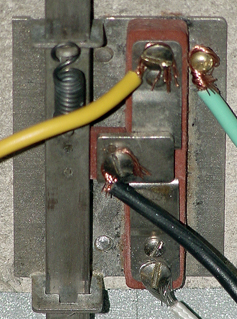
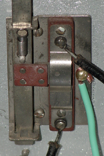
The above photo shows the switching mechanism for turning the safelight off and the white light on. When the contact printer is plugged into an outlet the safelight comes on. When the shaft on the switch is depressed the safeligjht goes off and the white light comes on. In this model the power is supplied through the center (black wire) which is touching the safelight contact (yellow wire). When the shaft is depressed the hot contact moves down and touches the white light contact (white wire at bottom). The shaft and contacts on this switch have to be precisely adjusted in order for the mechanism to operate as designed. The below (later model?) printer has a similar, but simpler switch.
![]()
The above photo shows what I believe is a later model of the Kodak Amateur Printer. Although it looks similar on the outside, there are significant differences inside.
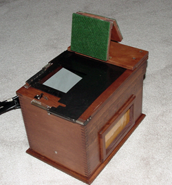
The photo on the above left shows the platen folded back exposing the glass and the adjustable metal sheets used for various sizes of print. The photo on the right shows the interior which is much simpler than the previous printer. The bulb positioning mechanism is no longer in place and the switch has been simplified (see below).
At first glance the above switch may appear the same as in the first printer, but it has only two contacts with wires attached rather than three (the green is merely a safety ground). The incoming hot wire is attached to the left side of the safe light (top contact in interior photo above). When the switch shaft is up as in this photo the current passes through the safelight and through the white light socket and bulb which is grounded thereby lighting the low wattage safelight. When the shaft is depressed the current passes through the black wired attached to the upper post on the switch and down through the lower black wire which is attached to left (upper post of the white light socket in the above photo) screw post on the high wattage white light. When the switch shaft is in the up position there is a slight space under the metal strip going between the two posts so that current cannot pass. When the shaft is depressed a metal piece attached to the center of the shaft (but insulated from the shaft) slides downward and electrically connects the upper post to the lower post. This system make uses of certain electrical rules in a clever way. When the shaft is up the current passes through the low wattage yellow bulb first lighting it up brightly and the high wattage bulb not at all. When the shaft is depressed the current goes to the white bulb dirrectly which is well grounded. This causes almost all of the current to go through the white bulb with virtually no current going through the yellow bulb, thus the white bulb lights brightly and the yellow bulb not at all. Information provided by Jack Carter, Sony technician. When you feel that you thoroughly understand the operation of the lighting system let us know and we will send you a 100 question test. 98% is a passing grade.
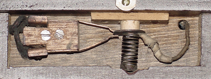
Homemade ContactPrinter. The printer below is the most unusual and undoubtedly the rarest of the three, possibly one of a kind. What is so unique is that it is not a Kodak Amateur Printer, but a homemade copy, and a very good one at that.
![]()
In addition to very good carpentry, the homemade printer has some very interesting features that perhaps Kodak should have copied. The wood bar across the top acts as a handle and as a means of depressing the switch. The Kodak switch is a thin metal bar that is not too kind to your fingers. Secondly, the post depressing the switch in the homemade copy is a round wooden peg, much safer than the metal shaft on the Kodak switch, especially as three-wire systems with safety grounds were not used in those days. The cleverest part of this printer is the simple switch that took the place of the Kodak switch. As you can see, it was made of a spring, a washer and two metal strips. The current comes through the wire on the right and passes through the upper metal strip when the peg is up thereby lighting the yellow bulb. When the peg is depressed the current goes through the lower strip and lights the white bulb. My hat is off to the builder of this gem of the early twentieth century.
www.nwmangum.com/ Kodak/AmPrinter-1.html
![]()
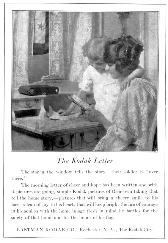
1918 Kodak advertisement in the National Geographic magazine
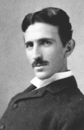
NIKOLI(A) TESLA - 1856-1943. Tesla invented radio, not Marconi. Tesla also invented the electric generator, the electric motor, fluorescent lighting, alternating current (AC) and devised the technologies that generate and deliver our electrical power for our homes, schools and factories. Tesla's discovery of the rotating magnetic field produced by the interactions of two and three phase alternating currents in a motor winding was one of the most significant achievements of the century and formed the basis of his induction motor and polyphase system for the generation and distribution of electricity. Tesla's generation of electricity resulted in what is known as alternating current, or AC. In alternating current the polarity and strength of the energy is continuously changing / alternating. In 1943, the Supreme Court granted full rights to Tesla for the invention of radio, nullifying the claims of Marchese Gugliemo Marconi who had patented a two-tuned-circuit design and a more practical four-tuned-circuit modeled after Tesla's. Marconi's patent on the invention of radio was overturned by the U.S. Supreme Court because Tesla's work predated it (Case #369, 6/21/43). Marconi did succeed in beating Tesla as the first person to send a wireless telegraph across the Atlantic which prompted Tesla to remark, "Let him continue. He is using seventeen of my patents." In addition, Tesla's 1903 patents 723,188 and 725,605 contains the basic principles of the logical AND circuit element basic to all computers.
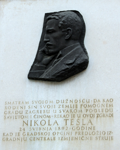
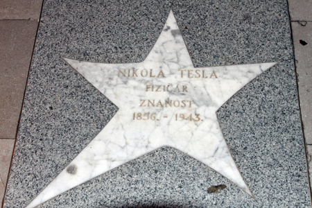
Tesla was born in Smiljan, Croatia, where he is considered a national hero. The plaque shown above is in Zagreb, the capital of Croatia, and the walkway star is in the City of Opatija.
For those of you wondering where to go on that once-in-a-lifetime trip you have been saving up for, you could make no better choice than Croatia. My wife and I have traveled to over 45 countries and we would place Croatia at the top of the list. Croatia has awesome scenic wonders, beautiful cities and towns with unforgettable architecture, is the cleanest country we have ever visited, and is absolutely safe day or night anywhere you might go. Our travel agency is Odysseys Unlimited which operates only with small tour groups of about 22-24 and always provides first-class hotel accomodations. Their current guide for Croatia (2010) is Darija Gotic, who is not only outstanding, but very easy on the eyes also.
http://www.viewzone.com/tesla.html http://
https://en.wikipedia.org/wiki/Nikola_Tesla
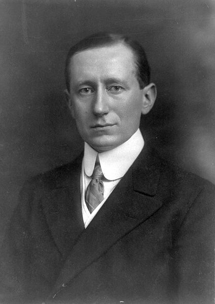
GUGLIELMO MARCONI - 1874-1937. Many people attribute the invention of radio to Marconi. It is more accurate to say that Guglielmo Marconi discovered a way to manipulate and exploit radio frequency energy. Marconi was actually one of many experimenters who were trying to send signals through the air rather than by wire, thus the name wireless. Marconi followed the developments of other inventors and in 1895 created his first successful wireless system. He patented his invention in England in 1896 and pursued the commercial aspects of wireless by installing his system on ships and at shore stations. On December 12, 1901, Marconi sent a signal from St. Johns Newfoundland to Poldhu, England. It consisted only of the letter S sent in telegraphic code but it was the first transatlantic broadcast of an electromagnetic signal or radio wave. Marconi's patent on the invention of radio was overturned by the U.S. Supreme Court because Nikoli Tesla's work predated it (Case #369, 6/21/43). Marconi did succeed in beating Tesla as the first person to send a wireless telegraph across the Atlantic, which prompted Tesla to remark, "Let him continue. He is using seventeen of my patents."
http://www.angelfire.com/ms3/n5ycn/history.html
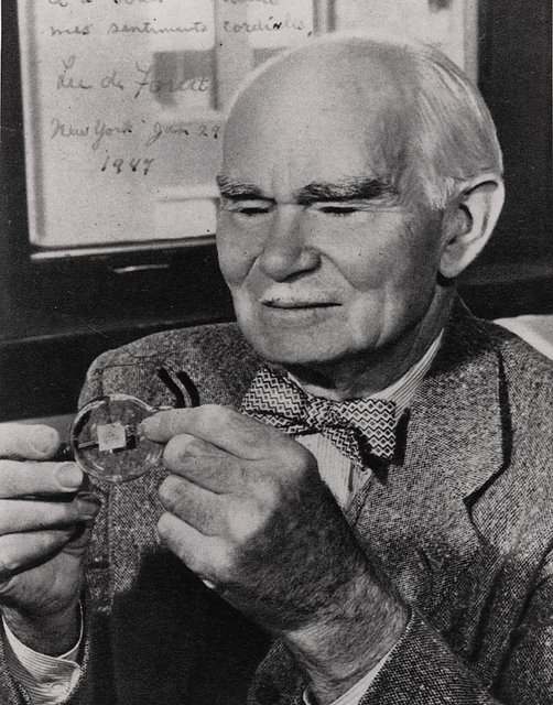
LEE DE FOREST - 1873-1961. In 1906, Lee De Forest invented what he called the Audion, the first Triode Electron Tube to successfully amplify radio waves. De Forest invented the device by inserting a grid into the center of a vacuum tube. Applying voltage to the grid controlled the amount of a second current flowing through the tube. This invention made coast to coast telephone calls possible. Soon, this triode tube was being used in radios as well. DeForest also challenged Edwin Armstrong's priority for the discovery of regenerative-oscillating, or feedback, circuit which greatly increased radio signals, made them loud enough to be heard across a room and led the way to transatlantic radio telegraphy, The issue was twice argued before the US Supreme Court which found in DeForest's favor due to a technical misunderstainding by the court. The scientific community has always credited Armstrong for the invention and he received a gold medal for it from the Institute of Radio Engineers.
http://www.angelfire.com/ms3/n5ycn/history.html
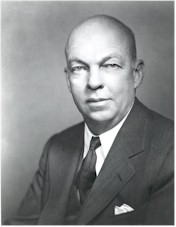
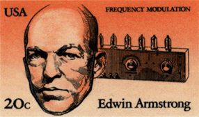
RADIO - EWIN HAROLD ARMSTRONG - 1890-1954. Guglielmo Marconi and Lee De Forest are the names that the public most frequently associates with the invention of radio, but in actuality, the contributions of those two individuals were relatively insignificant. Marconi followed the developments of others and discovered a way to manipulate and exploit radio frequency energy, creating a system that transmitted a telegraphic code of dots and dashes through the airwaves, but another scientist, Canadian Reginald A. Fesseden, devised the theory of the "continuous wave," a means of superimposing sound onto a radio wave. On December 23, 1900, Fesseden successfully transmitted the sound of a human voice between two 50-foot towers. In 1906, Lee de Forest invented the Audion, the first Triode Electron Tube to successfully amplify radio waves. While de Forest knew at the time he had made a significant discovery (and what would later prove to be his only successful invention), he could not explain how his Audion tube worked. Both he and Marconi spent the remainder of their days promoting themselves as the inventor of radio. De Forest went so far as to not only claim to be the "father of radio," but also the "grandfather of television."
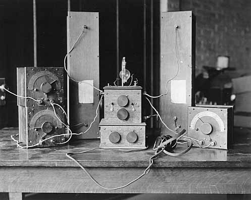
On December 12, 1914, Edwin H. Armstrong, an American electrical
engineer and a true genius, published an article in Electrical World
explaining the action of de Forest's Audion tube. Armstrong's
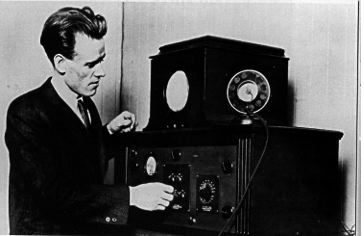
first important invention was the regenerative circuit he developed in
1912 (see photo above right). The regenerative circuit
revolutionized wireless radio communication because it could amplify
weak radio signals without distortion, and it did so far more
effectively than other radio receivers of the time. This
invention began radio's transition from a laboratory curiosity to the
ubiquitous household device that it is today. While serving in
the US Signal Corps in WWI, Armstrong came up with his second great
invention, the superheterodyne circuit. This invention allowed
for greater selectivity and amplification of radio signals. Prior
to Armstrong's superheterodyne radio, fading and static were constant
problems even when transmitting stations were located near to the
receiving radios. Automatically tuning into your favorite radio
station was an impossibility. If you were lucky, your favorite
station came in, and if not, some other station did - maybe.
Armstrong's technology, developed when most wireless stations were
still transmitting in Morse code, was an important step that would
allow future radio listeners to select a particular station and receive
it loudly enough so that it could be enjoyed.
Early on, Armstrong had entered into a series of court battles with Lee De Forest who claimed that he had been the inventor of the regenerative circuit, but just had not gotten around to applying for a patent. During one of his court appearances, De Forest spent more than three hours on the witness stand attempting to explain how the regenerative circuit worked, but was unable to do so. In one of the greatest ever travesties of American justice, the Supreme Court of the United States found in favor of De Forest over Armstrong due to a technical misunderstanding by the court. This decision was never accepted by those in the industry who knew that de Forest was nothing more than a backroom tinkerer who had serendipitously stumbled upon the beneficial effects of what he called the Audion tube. He had not only not invented the regenerative circuit, he had no idea how either it or his Audion tube worked.
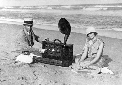
Armstrong's
present to his wife - a portable superheterodyne receiver, the world's
first portable radio.
In
1933, Armstrong introduced his third great invention in the development
of radio frequency modulation, or FM. This invention solved the
problem of noise and interference that plagued amplitude modulation
(AM)
stations of the time. During the early years of radio, an astute,
but ruthless businessman by the name of David Sarnoff had risen to
power
in the newly created Radio Corporation of America (RCA), eventually
becoming
the czar of America's empire of the air. Because RCA had such a
heavy
investment in AM radio, Sarnoff refused to adopt FM even though it was
vastly superior to AM. Instead, he used the great economic power
of RCA to impede the marketing of Armstrong's FM invention as much as
possible.
Armstrong then began his own company to promote FM and gradually made
inroads
into AM's radio monopoly. A great step forward came when the U.S.
Congress directed that FM be the means of voice transmission for
television.
This required all FM users to pay fees to Armstrong for rights to his
invention.
Sarnoff's reaction was to refuse payment and to urge all others to do
so.
This caused Armstrong to enter into legal contention with the industry
giant, RCA, and a number of other FM users - twenty-one lawsuits in
all.
After many years of legal battles, and with his own funds depleted,
Armstrong
became severely depressed and took his own life.
After
Armstrong's death, his widow continued the lawsuits her husband had
begun.
Her first victory came in 1954 over RCA and it gave her funds to
continue
the other suits. Finally, in 1967, with a victory over Motorola,
she had won all twenty-one of the lawsuits begun by her husband so many
years before. The name Edwin Armstrong is now synonymous with the
development
of modern radio.
http://www.angelfire.com/ms3/n5ycn/history.html
https://en.wikipedia.org/wiki/Edwin_Howard_Armstrong
PHILO T. FARNSWORTH TELEVISION - 1922.
A Utah-born Idaho farm boy, Philo T. Farnsworth created
television as we know it today. At fourteen, he visualized
trapping light in an empty jar and transmitting it one line at a time
onto a magnetically deflected beam of electrons. By the time
Farnsworth was 21 he had developed the first all-electronic system of
television. A 1922 Sketch by Farnsworth shown to his
high school physics and chemistry teacher illustrated how an image
might be electronically transmitted through the air to a receiver by
breaking the image up into a number of horizontal slices. This
image process which we now call a raster image occurred to Farnsworth
when as a fourteen-year old boy he looked across the rows of a field he
was plowing. In 1934 Farnsworth won a case before the U.S.
Supreme Court declaring that Farnsworth was the inventor of
television rather than Vladmir Zworykin
who was employed by David Sarnoff of RCA at that time. The case was won
when Farnsworth's high school physics teacher presented Farnsworth's
1922 sketch to the Court. The
attempt by Sarnoff to claim rights to television was similar to the
battle with Edwin Armstrong over radio. In both cases, Sarnoff was
eventually proven wrong in the courts. However, Sarnoff was able
to tie up Farnsworth in court for many years and cause him to expend
all his financial resources. Eventually, Sarnoff had to give in
to the inevitable and was about to pay Farnsworth a large sum in order
to use his patents, but just then the U.S. entered World War II and TV
research and production was put off for the next six years.
By that time Farnsworth's patents had run out and Sarnoff was able to
mass produce TVs under the RCA brand, bringing television to homes
throughout America by way of his TV network, NBC. In the end,
Farnsworth, the inventor of television, never profited from one of the
greatest inventions of all time, the riches instead going to Sarnoff
and RCA. Besides his contributions to
television, Farnsworth patented more than 130 inventions during his
lifetime.
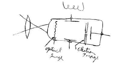
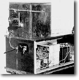
1922
Farnsworth High School Sketch of His TV Camera Tube and First
Farnsworth
TV Camera
Additional
information concerning Philo T, Farnsworth and television can be found
at:
https://en.wikipedia.org/wiki/Philo_Farnsworth
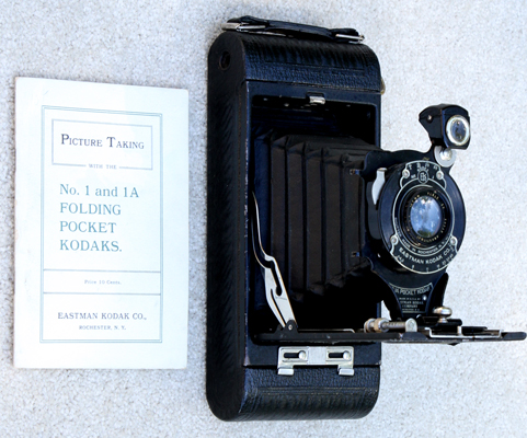
![]()
KODAK 1A POCKET CAMERA AUTOGRAPHIC - 1914-1924. Eastman Kodak produced a number of variations of this very popular camera thereby helping to promote the photography hobby in the U.S. The folding Pocket No. 1 (2 1/4" x 3 1/4" on 120 film) and No. 1A (2 1/2" x 4 1/4" on #116 obsolete film) came in various series and types. These cameras were mass produced with inexpensive optics. F/6.3 - F/45, 127mm lens (not same on all cameras). Kodex No 1 shutter (T,B.25,50). T he 1A Pocket Kodak was constructed of leatherette covered metal. The entire camera back was removed in order to load the film. It is one of the first cameras to incorporate an adjustable range finder. As the bellows is withdrawn from the body it extends on a chrome rail until it meets a stop. The supporting rail is then moved forward and back by means of a small thumb screw located on the right side. Distances were shown on a small scale on the left side. The stop is adjustable in order to calibrate the rangefinder. The 1A Autograhic camera was so called because it had one very unusual feature. There was a small sliding door on the rear which gave access to its special film which had a layer of carbon paper and a layer of thin red paper. Using a small stylus that came with the camera, it was possible to annotate handwritten remarks directly onto the film.
http://vieilalbum.com/1APocketKodakUS.hym
www.nwmangum.com/ Kodak/No1APK-1.html
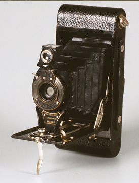
![]()
KODAK 2-A AUTOGRAPHIC BROWNIE - 1915-26. The 2-A was manufactured in Canada. From 1915 through 1916 the ends of the camera case were square. From 1917 through 1926 the ends were round as shown above. Kodex shutter with speeds B, T, 1/25, 1/50. The 2-A used size 116 film. MSRP $8-13.
http://www.camerapedia.org/wiki/Main_Page
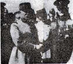
Sample Bartlane Print
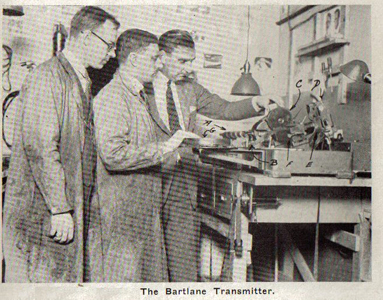
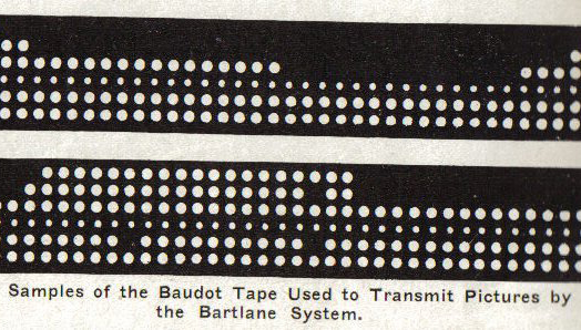
THE BARTLANE TRANSMISSION SYSTEM - 1920. The Bartlane facsimile system was named for Harry G. Bartholomew and Maynard D. McFarlane and was developed in Great Britain. It was one of the first applications of digital images as digitized newspaper pictures were sent by submarine cable between London and New York. Introduction of the Bartlane cable picture transmission system in the early 1920's reduced the time required to transport a picture across the Atlantic from more than a week to less than three hours. It utilized a punched tape, much like the old Wall Street ticker tape. The image was translated into variations of five-hole punches onto telegraphic tape and then transmitted, reversing the process at the other end. Pictures were coded for cable transmission and then reconstructed at the receiving end on a telegraph printer fitted with typefaces simulating a halftone pattern. Although it was an advance at the time, the resulting pictures looked like small, embroidered black and white pieces of paper. The early Bartlane systems were capable of coding images in five distinct brightness levels. This was increased to fifteen levels in 1929. As such, we might consider the Bartlane System to be an early form of a digital scanner. Additional information concerning the Bartlane system can be found at:
http://www.hffax.de/history/html/bartlane.html
1900-1920